The next few articles will outline the first tiny few steps towards achieving perfect capture sharpening, that is deconvolution of an image by the Point Spread Function (PSF) of the lens used to capture it. This is admittedly a complex subject, fraught with a myriad ever changing variables even in a lab, let alone in the field. But studying it can give a glimpse of the possibilities and insights into the processes involved.
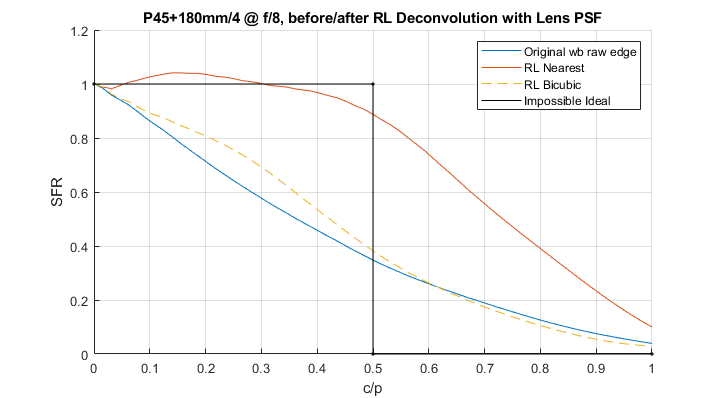
I will explain the steps I followed and show the resulting images and measurements. Jumping the gun, the blue line below represents the starting system Spatial Frequency Response (SFR)[1], the black one unattainable/undesirable perfection and the orange one the result of part of the process outlined in this series.
Figure 1. Spatial Frequency Response of the imaging system before and after Richardson-Lucy deconvolution by the PSF of the lens that captured the original image.
Goodman, in his excellent Introduction to Fourier Optics[1], describes how an image is formed on a camera sensing plane starting from first principles, that is electromagnetic propagation according to Maxwell’s wave equation. If you want the play by play account I highly recommend his math intensive book. But for the budding photographer it is sufficient to know what happens at the Exit Pupil of the lens because after that the transformations to Point Spread and Modulation Transfer Functions are straightforward, as we will show in this article.
The following diagram exemplifies the last few millimeters of the journey that light from the scene has to travel in order to be absorbed by a camera’s sensing medium. Light from the scene in the form of field arrives at the front of the lens. It goes through the lens being partly blocked and distorted by it as it arrives at its virtual back end, the Exit Pupil, we’ll call this blocking/distorting function . Other than in very simple cases, the Exit Pupil does not necessarily coincide with a specific physical element or Principal surface.[iv] It is a convenient mathematical construct which condenses all of the light transforming properties of a lens into a single plane.
The complex light field at the Exit Pupil’s two dimensional plane is then as shown below (not to scale, the product of the two arrays is element-by-element):
Figure 1. Simplified schematic diagram of the space between the exit pupil of a camera lens and its sensing plane. The space is assumed to be filled with air.
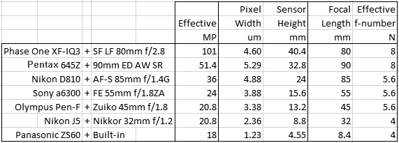
This post will continue looking at the spatial frequency response measured by MTF Mapper off slanted edges in DPReview.com raw captures and relative fits by the ‘sharpness’ model discussed in the last few articles. The model takes the physical parameters of the digital camera and lens as inputs and produces theoretical directional system MTF curves comparable to measured data. As we will see the model seems to be able to simulate these systems well – at least within this limited set of parameters.
The following fits refer to the green channel of a number of interchangeable lens digital camera systems with different lenses, pixel sizes and formats – from the current Medium Format 100MP champ to the 1/2.3″ 18MP sensor size also sometimes found in the best smartphones. Here is the roster with the cameras as set up:
We now know how to calculate the two dimensional Modulation Transfer Function of a perfect lens affected by diffraction, defocus and third order Spherical Aberration – under monochromatic light at the given wavelength and f-number. In digital photography however we almost never deal with light of a single wavelength. So what effect does an illuminant with a wide spectral power distribution, going through the color filter of a typical digital camera CFA before the sensor have on the spatial frequency responses discussed thus far?
 arrives at the front of the lens. It goes through the lens being partly blocked and distorted by it as it arrives at its virtual back end, the Exit Pupil, we’ll call this blocking/distorting function
  . Other than in very simple cases, the Exit Pupil does not necessarily coincide with a specific physical element or Principal surface.
 plane is then
  as shown below (not to scale, the product of the two arrays is element-by-element):